Newsletter
Stay connected
Stay informed with our newsletters! Get the latest software release news, dive into cutting-edge fatigue analysis with FEMFAT, discover exciting events and training opportunities and explore captivating case studies. Plus, we're here to answer your FAQs. Join us and explore the world of engineering excellence!
Subscribe to our Newsletter
Newsletter 34/2025
Review of Magna ECS SimCo and FEMFAT User Meeting, Release Highlights FEMFAT 2025, New Feature: Deformation Animation, HARMONIC: Multi Sine Excitation, Upcoming Road Shows & Trainings, 2 FAQs
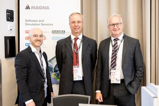
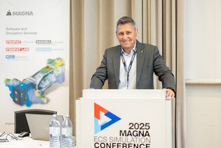
Magna ECS Simulation Conference 2025 – A Look Back
From May 14–15, the Magna ECS Simulation Conference once again brought together simulation enthusiasts, engineers, and industry experts in Waidhofen/Ybbs, Austria.
Set against the historic backdrop of Schloss an der Eisentrasse, the event welcomed 130 participants from 17 countries. With four focus areas FEMFAT, KULI, Dynamics, and FEMFAT LAB it offered a compelling mix of technical depth and relaxed networking opportunities.
The day before the conference kicked off, newcomers got hands-on insights during the FEMFAT Newcomer Workshop, while the day after the conference featured four advanced workshops for deep dives into fatigue simulation with FEMFAT. The conference itself included 46 presentations covering a broad spectrum of simulation topics.
The FEMFAT User Meeting, part of the conference, saw 70 participants engaging in 15 presentations and a guest lecture. A special highlight was the plenary lecture by Dr. Clara Schuecker from Technical University of Leoben, discussing damage mechanisms in laminate materials and stiffness degradation.
Another standout moment was the guest lecture by Bruno Buchberger from JKU Linz, titled "Invention in the AI Age". Mr. Buchberger shared insights from his decades of experience in mathematics, computer science, and innovation management. Drawing from his method of “Positive Tension Management”, he demonstrated how structured creativity can lead to groundbreaking ideas – even in complex or seemingly contradictory situations.
The thematic breadth of presentations and workshops was impressive, covering key areas such as
- Fatigue assessment of welded joints, with a focus on aluminum components, chassis structures, and crane parts
- Digital twin methodology and AI-powered fatigue life monitoring, showcasing innovative approaches to predictive maintenance
- Thermomechanical fatigue simulation, including detailed studies on pistons and cylinder heads
- Fatigue evaluation of electronic components and cables, addressing reliability in increasingly complex systems
- Transient fatigue analysis, considering dynamic contact scenarios and elastomeric interactions
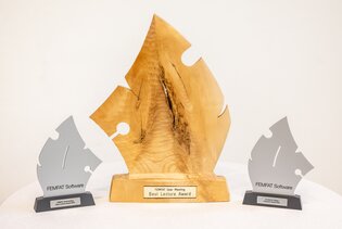
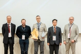
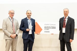
The event also featured the awarding of the Academic Fatigue Research Award, recognizing outstanding scientific contributions in fatigue research. The Best Lecture Award was presented to Marton Graf from GDLS for his excellent presentation.
Want to revisit the presentations or learn more?
Visit ecs-simulation-conference.com for downloads and insights.
The International FEMFAT User Meeting 2025 was a resounding success, providing an excellent platform for the exchange of knowledge and experiences in simulation and fatigue analysis. We look forward to the next meeting and the exciting developments that await us.


FEMFAT 2025 Release Highlights
We are excited to announce the latest enhancements in our FEMFAT software, designed to streamline your workflow and elevate your analysis capabilities. Here are the key features of this release:
Auto-Detection for FE Structure Interface
Say goodbye to manual format selection!
Our new "Auto detect" feature automatically identifies and imports any structural file format. This smart detection is now the default setting, ensuring a seamless integration into your projects.
Drag’n’Drop Functionality for Input Files
Simplify your file management with the new drag-and-drop feature. Easily import ffj files, FE entities, stress files, and load history files directly into FEMFAT on Windows (WIN64). This intuitive functionality saves time and effort.
Display of Multiple Material Haigh Diagrams
Visualize and compare multiple material Haigh diagrams simultaneously in the Material Data menu. Select from a list of available material curves and customize your view by showing or hiding diagrams as needed.
New Equivalent Stress Methods: COIN LiWI and FKM LiWI in MAX
Enhance your stress analysis with two new methods available in MAX: the COIN LiWI Method and the FKM LiWI Method. These advanced techniques utilize complex invariants in the frequency domain to provide a fast and accurate alternative to already existing equivalent stress computation methods.
ChannelMAX: Generation of Animation Data
Create detailed deformation animations based on critical damage events, user-defined time ranges, or automatically detected critical periods. Export the data in CSV and/or RPC Binary formats for use in post-processors like ANIMATOR, META, or Hyperview.
SPECTRAL: Force-Based Assessment of SPOTs
Introducing SPOT FORCE analyses in SPECTRAL!
This new feature adds a force-based method to the SPOT assessment in random response fatigue analyses.
Automatic Material Assignment for Abaqus Interface
Experience enhanced automation with the expanded *.fma file table, now including a "Groupname" column. Automatically assign materials for ABAQUS interfaces and create material sets directly from ABAQUS *.odb or *.inp files. This feature ensures precise material mapping and efficient group management.
Improved Stress Gradient Influence Method
We’ve refined the stress gradient influence method for more accurate analysis:
-
Nodes with increasing stress in all directions now use the smallest absolute value of negative gradients.
-
In line with the FKM Guideline, a linear function is now applied for stress gradients Χ′ < 0.1 mm⁻¹. This results in a reduced support effect for smaller gradients compared to the previous method.
We are confident that these new features will significantly enhance your FEMFAT experience and provide you with powerful tools to tackle complex engineering challenges.
Thank you for your continued support and feedback.
FEMFAT 2025: Visualize Fatigue-Critical Deformations with New Animation Export Feature
In the course of development, engineers not only need to assess the extent of damage but also determine how to improve critical areas. In multi-axial applications, ChannelMAX calculates damage through multiple channels, which are superimposed over time. This complexity can make it challenging to devise effective improvement strategies.
With FEMFAT 2025's new feature, users can export data to visualize deformations during damage-relevant time periods or selected intervals. By visualizing deformation during critical periods, engineers can better interpret damage mechanisms and develop targeted design improvements.
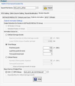
Where to Find It
The new animation export feature is available in ChannelMAX, under the “Output” menu. Within this section, navigate to the “Module Specific” tab, and then to the “Data for Animation” sub-tab to configure and export deformation data.
What’s New?
FEMFAT 2025 introduces a dedicated “Data for Animation” export function within ChannelMAX, allowing users to generate time-resolved deformation data for selected nodes or node groups. This data can be animated in external postprocessors (Meta, HyperView, Animator) to visualize how the structure behaves during:
-
Critical Damage Events
-
User-defined Time Ranges
-
Automatically detected Critical Periods
How It Works
To use this feature, a ChannelMAX damage analysis must be performed in the current FEMFAT session. After the analysis, the user needs to open the “Data for Animation” menu and select one of the three options described above:
• Critical Damage Events
• User-defined Time Ranges
• Automatically detected Critical Periods
Once the desired option is selected and its parameters specified, clicking the “Write” icon will generate the animation data.
The exported animation data reflects the deformation history across selected time intervals and channels, and is available in two formats:
-
CSV (.aof) – tabular format without headers, ideal for quick integration.
-
Binary RPC (.tim) – includes headers, suitable for advanced postprocessing.
Depending on the selected mode, the output can be:
-
Node-specific (with individual files per node and optional cycle-wise separation)
-
Global (for time-range-based animations without node separation)
Input Requirements
-
ChannelMAX analysis with damage as the calculation target.
-
Rainflow counting method: FEMFAT 5.1
-
DETAILED RESULTS group (required for damage-based animations)
-
Selection of one of the following export modes:
-
Critical Damage Events – based on descending damage magnitude, with optional threshold filtering and cycle-wise export.
-
Time Range – user-defined start/end times with adjustable time increments.
-
Critical Period – automatic detection of the time interval with the highest damage sum.
-
Output & Postprocessing
Once configured, the animation data can be exported and imported into supported postprocessors. Engineers can then:
-
Animate deformation over time
-
Superimpose stress tensors
-
Visualize load cycles and damage evolution
This turns abstract fatigue results into tangible insights, helping engineers identify root causes and validate design improvements with confidence.
Why It Matters
This feature empowers FEMFAT users to move beyond static damage values and into the realm of dynamic understanding. By visualizing how structures deform under real-world loading conditions, engineers can:
-
Detect critical load interactions
-
Understand damage progression
-
Communicate findings more effectively
Whether you're troubleshooting a failure or optimizing a design, FEMFAT 2025’s animation export capability is a game-changer for fatigue analysis workflows.
Efficient Multi-Sine Sweep Simulation with HARMONIC
Vibration testing can be time-consuming, especially when a wide frequency range needs to be covered. That’s where Multi-Sine vibration testing comes in: by splitting up the frequency range in several segments and sweeping them simultaneously, engineers can significantly reduce test time. This is particularly useful for fatigue testing, where traditional methods often require many hours of repetitive sweeps.
Good news is as of HARMONIC 2025, you can now easily simulate both linear and logarithmic Multi-Sine Sweeps.
How it works
In HARMONIC, Multi-Sine Sweeps can be defined using either linear or logarithmic frequency scales – just like traditional sine sweeps. For both types, there are three flexible ways to define your sweep setup.
(Helpful tip: The installation package includes example configuration files for all options.)
Definition Options:
Option | Parameters |
1 | Start frequency, End frequency, Duration of one Sub-Sweep, Number of Sub-Sweeps |
2 | Start frequency, Frequency increment, Time increment, End frequency |
3 | Start frequency, Frequency increment, Time increment, Duration of one Sub-Sweep, Number of Sub-Sweeps |
Example
Let’s say you define a linear Multi-Sine Sweep like this:
-
Start Frequency: 1 Hz
-
End Frequency: 13 Hz
-
Duration per Sub-Sweep: 3 seconds
-
Number of Multi-Sines: 4
HARMONIC will automatically split the frequency range into four segments. For each load case, you’ll get csv files with modal coordinates for
-
Segment 1: 1–4 Hz
-
Segment 2: 4–7 Hz
-
Segment 3: 7–10 Hz
-
Segment 4: 10–13 Hz
-
Superimposed result: All segments combined
If you define multiple load cases, HARMONIC will also generate a combined result file across all segments and load cases.
This gives you full flexibility to analyze fatigue behavior – whether you want to look at individual segments, specific load cases, or the full picture.
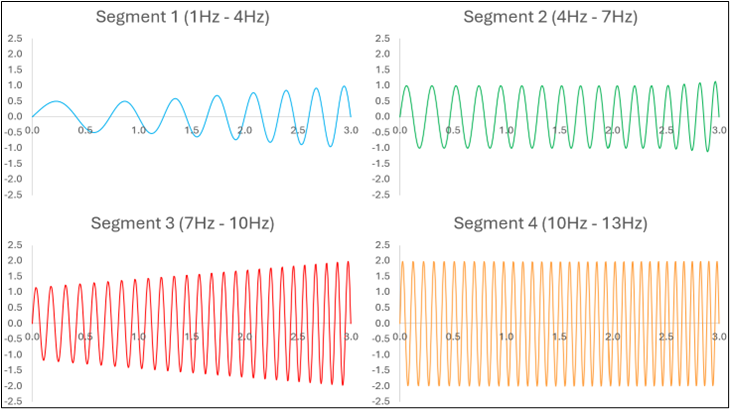
Figure 1: Modal coordinates for Mode 1, Load Case 1, segmented view
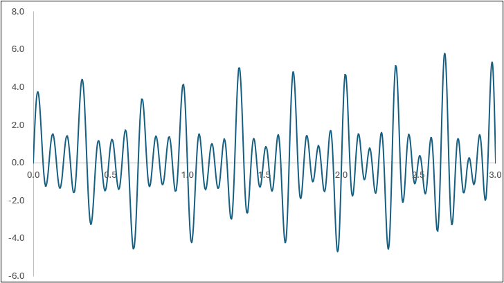
Figure 2: Modal coordinates for Mode 1, Load Case 1, superimposed view
Conclusion
Multi-Sine Sweep simulation in HARMONIC is a powerful tool for efficient and accurate vibration analysis. By sweeping multiple frequency segments at once, you save time and gain deeper insights into resonance behavior helping you make better design decisions and improve structural durability.
Dates for Road Shows & Training
Events
| Date | Title | Location |
|---|---|---|
| 07–08 Oct 2025 | DVM Structural Integrity and Product Lifecycle – From Design to Circular Economy | Berlin, Germany |
| 07 Oct 2025 | CADFEM Conference Künzelsau | Künzelsau, Germany |
| 10 Oct 2025 | Ansys Simulation World 2025 Japan | Tokyo, Japan |
| 14 Oct 2025 | FEMFAT Roadshow – Magdeburg | Magdeburg, Germany |
| 16 Oct 2025 | FEMFAT Roadshow – Münster | Münster, Germany |
| 20–21 Oct 2025 | FEMFAT Usermeeting China | Shanghai, China |
| 20–23 Oct 2025 | International Conference on Residual Stresses | Detroit, USA |
| 04 Nov 2025 | CADFEM Conference Salzburg | Salzburg, Austria |
| 19 Nov 2025 | FEMFAT Usermeeting Korea | Seoul, Korea |
| |
Trainings
| Date | Title | Location |
|---|---|---|
| 20–21 Oct 2025 | FEMFAT Standard Training Japan (1st) - BIW / Chassis) | Online |
| 21–24 Oct 2025 | FEMFAT Standard Training | Online |
| 28–29 Oct 2025 | FEMFAT Advanced Training – MAX | Online |
| 24–27 Nov 2025 | FEMFAT Standard Training (suitable for North America) | Online |
| 02–03 Dec 2025 | FEMFAT Advanced Training – SPECTRAL | Online |
| 27–30 Jan 2026 | FEMFAT Standard Training | Online |
| 03–04 Feb 2026 | FEMFAT Advanced Training – Material | Online |
| 03–04 Mar 2026 | FEMFAT Standard Training | St. Valentin, Austria |
| 10–11 Mar 2026 | FEMFAT Advanced Training – Non-Metal Fatigue | Online |
| 13–16 Apr 2026 | FEMFAT Standard Training (suitable for North America) | Online |
| 21–22 Apr 2026 | FEMFAT Advanced Training – WELD | Online |
| 09–12 Jun 2026 | FEMFAT Standard Training | Online |
| 16–17 Jun 2026 | FEMFAT Advanced Training – SPECTRAL | Online |
| |
Frequently Asked Questions
FAQ1: How is stress calculated in the Check Input Data file (*.cid)?
Check Category "Module basic" for ANSWER
FAQ2: How are combined WELD nodes treated in FEMFAT during notch stress calculation?
Check Category "Module weld" for ANSWER
