Newsletter
Stay connected
Stay informed with our newsletters! Get the latest software release news, dive into cutting-edge fatigue analysis with FEMFAT, discover exciting events and training opportunities and explore captivating case studies. Plus, we're here to answer your FAQs. Join us and explore the world of engineering excellence!
Subscribe to our Newsletter
Newsletter 30/2023
FEMFAT 2022; Fatigue Strength Assessment acc. to the FKM Guideline in FEMFAT – (1/3); Events & Trainings; FAQ
FEMFAT 2022
With FEMFAT 2022, the new FEMFAT version you can expect a colorful mixture of new functionalities and numerous program improvements. Selected points are briefly introduced below:
- VISUALIZER: new graphics kernel & support of space mouse
- Multi-Segment S/N curve: definition of properties for LCF, HCF & VHCF
- Vector Reconstruction gradient method as default setting in BASIC, MAX & SPECTRAL
- Point coordinates display in diagrams (Haigh, S/N, History Charts)
- SPECTRAL: Steinberg three-band method
- Automated material assignment for WELD and SPOT nodes
- Interfaces: support of Abaqus 2022 & H3D 2021
- ALTAIR Licensing for FEMFAT inside ANSYS
- Output for beam elements in ChannelMAX: export superimposed channel forces and moments into csv files
- and many more
Some new features of FEMFAT 2022 in brief:
VISUALIZER: new graphics kernel & support of space mouse
The new kernel of the VISUALIZER improves the transparency of the elements and the performance of large models. In addition, it is the basis for many of the other new features such as element-based fading, adjustable screenshot resolution or the new feature lines. It is now possible too, to use the Space Mouse from 3DConnexion under Windows.
Multi-Segment S/N curve: definition of properties for LCF, HCF & VHCF
There is now a second SN curve model for materials in FEMFAT 2022: The multi-segment model. For multi-segment materials, in addition to the classical type-dependent parameters, the slope and the number of cycles must be specified for the LCF (Low Cycle Fatigue) area and the VHCF (Very High Cycle Fatigue) area.
Vector Reconstruction gradient method as default setting in BASIC, MAX & SPECTRAL
As of version FEMFAT 2022, the gradient calculation method "Vector reconstruction" will be used as default method for the modules BASIC, TransMAX and SPECTRAL. In ChannelMAX the method "Vector reconstruction reduced" is used by default. FEMFAT job files created with an older version are not affected by this and are evaluated with gradient calculation method FEMFAT 2.4, unless another selection was explicitly made.
Point coordinates display in diagrams (Haigh, S/N, History Charts)
From FEMFAT 2022 it is possible to display/mark certain coordinates in diagrams (knee points, critical points, linear interpolations between points, etc.). This applies analogously to the amplitude class bars in the SN curve of a damage calculation.
SPECTRAL: Steinberg three-band method
A new template is now available for SPECTRAL (Steinberg_for_SPECTRAL), which can be used to perform a damage analysis according to the Steinberg three-band method. This template can be called after all preparations for a SPECTRAL analysis have been made (FE structure read in, material defined, loads defined, etc.).
Automated material assignment for WELD and SPOT nodes
With FEMFAT 2022, after executing the material assignment table of a FEMFAT material assignment file (.fma file supported since FEMFAT 5.4.3), two switches can be used to control whether an automatic material assignment/completion to SPOT/WELD nodes should also be performed.
Interfaces: support of Abaqus 2022 & H3D 2021
With the release FEMFAT 2022, the FE-adapter was updated for ABAQUS 2022. The odb user can use the versions 2017, 2018, 2019, 2020, 2021 and 2022. Geometry support for Altair H3D library 2021 has been added, which allows reading 2021 H3D files.
ALTAIR Licensing for FEMFAT inside ANSYS
It is now possible to run FEMFAT in ANSYS Workbench - the extension "FEMFAT inside ANSYS" - via Altair licensing (Altair Partner Alliance).
Output for beam elements in ChannelMAX: export superimposed channel forces and moments into csv files
Within the ChannelMAX module, FEMFAT 2022 offers the possibility to output superimposed channel forces and moments for a predefined group of beam elements into csv files.
Fatigue Strength Assessment acc. to the FKM Guideline in FEMFAT
Assessment with local stresses in base material (1/3)
Consideration of stress and material parameters for Assessment with local stresses in the base material
In the FEMFAT software, the fatigue strength assessment can be conducted according to the FKM guideline, optionally taking into account methods that have been successfully established in practice for many years. An example of this is the cutting plane concept for multi-axial loads available in FEMFAT and mentioned in FKM guideline edition 7 (abrev. FKM7).
In FEMFAT, local stress parameters calculated by means of FEM and averaged at the nodes are the basis for the assessment in the base material. As of version 5.4.3, the total influence factor ftot,af acting on the fatigue strength can now also be combined acc. to FKM
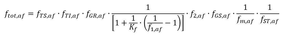
In addition to influencing factors for taking into account the material properties,
| fTS,af | technological size influence factor |
| fTI,af | thermal influence factor |
the equation also includes influencing factors for taking into account the design parameters
| fGR,af | stress gradient influence factor |
| Kf | estimated fatigue notch factor |
| f1,af | surface roughness (and degree of forging) influence factor |
| f2,af | technological surface treatment influence factor |
| fGS,af | general surface factor |
and the component strength
| fm,af | mean stress influence factor |
| fST,af | statistical influence factor |
For the assessment, all those influence factors (relevant for the respective component) must be taken into account for which a method “FKM Guideline” is available. Influences on the inclination and the cycle limit of the component S/N curve remain deactivated.
Characteristic values of stress
In the FKM guideline, the component surface is considered. The following applies to the plane stress state
σx, σy, τ = τxy
and for the general triaxial stress state
σx, σy, τ = τxy, σz = σ3
In FEMFAT, at base material nodes the method of the critical cutting plane is used (see section 4.6.2.2 'Procedure for rotating principal stresses' in FKM7). The characteristic stress values are the normal stresses \sigma σ and shear stresses \tau τ occurring in the cutting plane.
For MAX it can be selected whether the assessment in the cutting plane on the surface is to be based on a
- planar stress state (2D, Surface Nodes) or a
- 3D stress state (3D, Surface Nodes)
For BASIC, a 3D stress state is assumed at all FE nodes (corresponds to 3D, All nodes in MAX). For a 3D stress state, FEMFAT considers the transmission of shear stresses (σz ≠ σ3).
Material Properties
In the FKM guideline, the material fatigue strength for tension-compression σW,zd and shear τW,s is estimated from the normative component standard value of the tensile strength Rm.
σW,zd = fW,σ ⋅ Rm
τW,s = fW,σ ⋅ Rm ⋅ fW,τ
The factors fW,σ and fW,τ (FKM7, tab. 4.2.1) are implemented in the FEMFAT material generator, where the shear values apply to homogeneous loading (note: a torsion specimen with specimen diameter d is subjected to inhomogeneous loading due to the 2/d stress gradient). In the FKM guideline, the normative component values of tensile strength Rm and yield strength Rp are estimated from the normative material values Rm,N and Rp,N, taking into account the technological size factors Kd,m, Kd,p and Kd,A, as well as the anisotropy factor KA (FKM7, Section 3.2.1.2).
Rm = Kd,m ⋅ KA ⋅ Rm,N
Rp = Kd,p ⋅ KA ⋅ Rp,N
A = Kd,A ⋅ A
In addition, the material fatigue strength values are reduced by means of a temperature factor KT,D (FKM7, ch. 4.2.3) to values for high temperature.
σW,zd,T = KT,D ⋅ σW,zd
τW,s,T = KT,D ⋅ τW,s
The factors Kd,m, Kd,p, Kd,A and KT,D are usually not included in the material generation in FEMFAT, because they are considered in the influence factor method (see FEMFAT Influence Factors below). With an anisotropy factor KA=1, the normative material strength values Rm,N and Rp,N (FKM7, chapter 5.1) can be entered directly into the Material Generator.
FEMFAT Material Data:
Technological Size
The parameters deff,N,m, deff,N,p, ad,m and ad,p for determining the technological size factors Kd,m and Kd,p (FKM7, chap. 3.2.1.4) were previously defined in the FKM guideline for material classes (FKM6, Table 3.2.1 and 3.2.2). In FEMFAT, the values are therefore stored in userdefparam.dbs. In the current FKM guideline, the values have been assigned directly to the materials (FKM7, chap. 5.1). Since the values can vary within a material class, it is recommended to assign the parameters in FEMFAT material.
FEMFAT Influence Factors:
Technological Size
The technological size factors of tensile strength Kd,m(deff,N,m,ad,m) and yield strength Kd,p(deff,N,p,ad,p) can be considered in FEMFAT for steel and cast iron materials, as well as for wrought aluminum materials according to the 'FKM Guideline' (FKM7, chap. 3.2.1.4) can be taken into account. The equations for cast aluminum materials (FKM7, Eqs. 3.2.10 to 3.2.12) are included since FEMFAT 2022 version, but the previous formulas give similar results. The size factor of elongation at rupture Kd,A(deff,N,A,ad,A) has not been implemented yet.
For nodes on shell elements, the effective diameter deff needed to calculate the technological size factor is determined from the thicknesses of the adjacent elements. For nodes on 3D elements, the assignment is done by means of node characteristic (FKM7, Tab. 3.2.1).
Temperature
The determination of the temperature factor KT,D = fTI,af is possible in FEMFAT with the method 'FKM guideline' (FKM7, chapter 4.2.3). The temperature factor is applied to the material fatigue limit for normal and shear stress together with other factors (see 1.1 Fatigue strength assessment). The material ductility k which is taken into account in the “Scaled Normal Stress in Critical Plane".
k = σW,zd / τW,s = (KT,D ⋅ σW,z) / (KT,D ⋅ τW,s)
does not change when the temperature factor is considered. For the 'Critical component Critical Plane' method, the temperature factor KT,D is applied equally in the material fatigue limit for normal and shear stress, resulting in an FKM-compliant result. The equations depend on the material class for the 'FKM Guideline' method. The static strength values remain unchanged for this method. The temperature T is assigned to the FE nodes as a node characteristic.
Events & Trainings
In the year 2023 we offer again a wide range of events:
- ECS Simulation Conference 2023
- Basic Trainings for the introduction to FEMFAT
- Advanced Trainings for special modules and needs of our advanced users.
We offer different trainings in 2023:
All trainings will be held in German or English as required.
- Find your Standard Training
- Find your Advanced Training
Are you interested in actively participating in one of the events?
Go to events and trainings and register!
EVENTS & TRAININGS
Frequently Asked Questions
FAQ 1: How is the automatic material assignment done in FEMFAT?
FAQ 2: Why is there a new method ("Vector Reconstruction") for the stress gradient calculation?
VIEW ANSWER
FAQ 3: How does FEMFAT manage the odb files?
VIEW ANSWER
BACK TO OVERVIEW
