时事通讯
保持联系
通过我们的时事通讯了解最新信息!获取最新的软件发布消息,利用 FEMFAT 深入了解最前沿的疲劳分析,发现令人兴奋的活动和培训机会,并探索引人入胜的案例研究。此外,我们还为您解答常见问题。加入我们,探索卓越工程世界!
订阅电子报
Newsletter 31/2023
Highlights - ECS Simulation Conference 2023; New Features of FEMFAT 2023; Introducing an enhanced Neuber approach with new PLAST method; Fatigue Strength Assessment acc. to the FKM Guideline in FEMFAT (2/3); FAQ
Inside the Summit: Highlights from the ECS Simulation Conference 2023
Introducing the must-attend event in the automotive industry - the International FEMFAT User Meeting, now a successful part of the prestigious ECS Simulation Conference. This event unites user meetings for our complete range of ECS software products (including FEMFAT, FEMFAT LAB, and KULI) alongside the highly anticipated ECS-Dynamics Conference. After the challenges posed by the COVID-19 pandemic, we were thrilled to welcome our valued guests for an in-person experience this time.
Relocating to the magnificent Voest Alpine Stahlwelt in Linz, we saw more than 90 participants immerse themselves in the world of fatigue analysis with FEMFAT through 18 captivating user presentations. From cars, trucks, and motorcycles to e-fueled combustion engines, the discussions covered everything from welded joints to fiber-reinforced plastics, along with groundbreaking methods and processes.
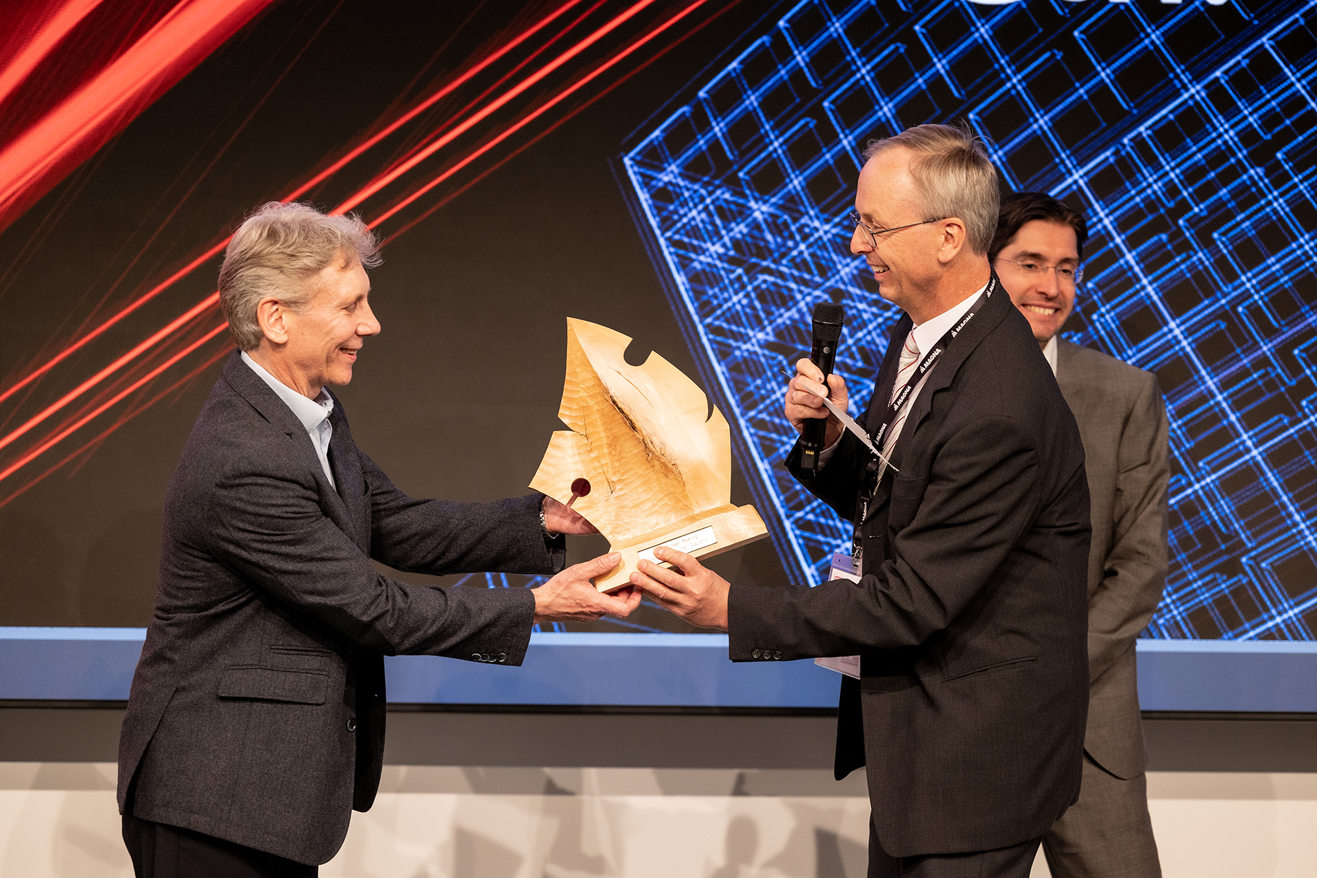
Highlighting the prowess of our community, the prestigious "Best Lecture Award" recognized the outstanding work of Michael DeJack (AVL) on the fatigue life evaluation of case-hardened gears. Michael's groundbreaking investigations shed light on the critical crack initiation locations within the gears. In these components, the location of crack initiation was either in the hardened layer (for high loads) or in the unhardened core (for lower loads), depending on the load level. Based on specimen tests, FEMFAT material data for these two crack initiation locations were determined and applied. An FE model for calculating the rolling contact in ABAQUS was also developed for this purpose. The simulation method was validated (in terms of contact pattern and strain) with a special test rig test for differential gears and showed excellent correlation with the fatigue life calculated by FEMFAT.
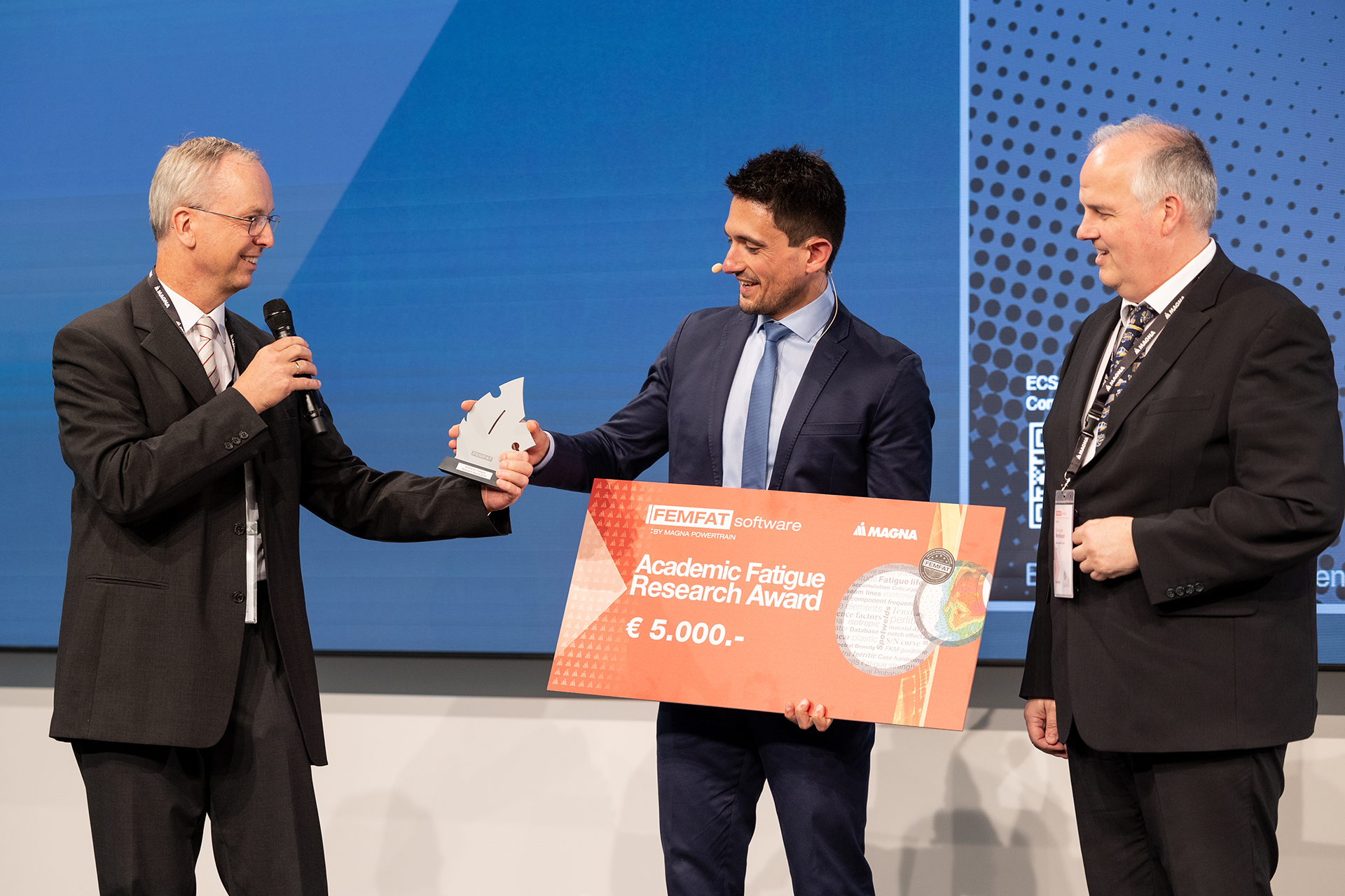
Further enriching the event the "Academic Fatigue Research Award " was presented during the FEMFAT User Meeting for the third time. This award honors scientific works focused on fatigue life and durability, as well as applications and future developments in fatigue life prediction. We proudly presented the "Academic Fatigue Research Award " to Dr. Serkan Cavdar (Henkel) for his exceptional doctoral research on hyperelastic bonded joints.
To complement the wealth of knowledge shared, the conference offered immersive workshops, engaging evening events, and the chance to explore the breathtaking Stahlwelt and historic city of Linz.
Once more, the ECS Simulation Conference exceeded expectations as an outstanding platform for knowledge exchange, captivating discussions, and invaluable networking opportunities in the dynamic realm of fatigue simulation and beyond.


Fatigue Strength Assessment acc. to the FKM Guideline in FEMFAT
Assessment with local stresses in base material (2/3)
Continuation of the article recently published in FEMFAT Newsletter #30 on FKM-compliant fatigue strength assessment of the base material (1/3), this time focusing on the consideration of design factors.
Since FEMFAT 2023 it is possible to assess the fatigue strength of non-welded and shell-meshed welded components according to the 7th edition of the FKM guideline 2020 'Analytical Strength Assessment for Components in Mechanical Engineering' (abbr. FKM7). Particularly in view of the complexity of the guideline, the aim was to provide a defined simulation process for the software-based assessment. This has been standardized by a template that can be loaded directly from the GUI following project-specific inputs. At this point the accompanying manual (FEMFAT_Template_FKM) should be highlighted, which explains all the details including the material generation.
Design parameters
For the combination of influences acc. to the 'FKM Guideline', the design factor KWK (FKM7, eq. 4.3.1) was integrated into the equation of the total influence on the fatigue limit ftot,af (see Newsletter #30 for details)

- nσ Kt - Kf ratio (= fGR,af)
- Kf,σ estimated fatigue notch factor (= Kf)
- KR,σ roughness factor (= f1,af)
- KV surface treatment factor (= f2,af)
- KS coating factor (= fGS,af / KNL,E,σ ∙ jS ∙ jF,b ∙ jG,b)
- KNL,E,σ factor for GJL under bending (= fGS,af / KS ∙ jS ∙ jF,b ∙ jG,b)
The FKM guideline determines the design parameter for normal and shear stresses. Differences for shear stresses arise in the determination of the Kt - Kf ratio (nτ), the estimated fatigue notch factor (Kf,τ) and the roughness factor (KR,τ). The constant KNL,E,σ is only relevant for normal stresses. In contrast, in FEMFAT a total influence factor ftot,af is applied equally to normal and shear stresses.
FEMFAT Material Data
The equations of the design factors are hard coded in FEMFAT, i.e. additionally to the material generation acc. to FKM (Material Generator 2023) no material data need to be defined for the implemented 'FKM Guideline' methods described in the following sections.
FEMFAT Influence Factors
Relative stress gradient
The constant Kf can be assigned as node characteristic from FEMFAT 5.4.3 onwards and is considered in the same way for normal and shear stresses. As an approximation, for not too mild notches (stress concentration factor Kt ≥ estimated fatigue notch factor Kf) can be taken from FKM7 tab. 4.3.1. Alternatively, eq. 4.3.2 which depends on the stress concentration factor Kt and the Kt - Kf ratio n) is also available for estimation.
In FEMFAT with the 'FKM Guideline' method, the Kt - Kf ratio n(X’max) = fGR,af is determined acc. to SIEBEL & STIELER (FKM7, sec. 4.3.1.3.1). The relative stress gradient X’ is determined based on the v.Mises stress. In this, FEMFAT differs from the FKM guideline, which here treats the normal and shear stress separately from each other (FKM7, sec. 4.3.1.3.3). Properties from surface hardening can be considered in materials assigned to the boundary layer of the component.
The FKM guideline edition 7 describes, as an alternative to the Kt - Kf ratio acc. to SIEBEL & STIELER, the determination of a material-mechanical Kt - Kf ratio (FKM7, sec. 4.3.1.3.2). The concept is currently not available in FEMFAT, but from version 2022, externally determined stress factors and/or gradients can be assigned as node characteristics.
Surface roughness
The roughness factor KR of the FKM considers the influence of the surface roughness (in µm, acc. to DIN 4768) on the fatigue strength. In FEMFAT, the equation for normal stresses (FKM7, eq. 4.3.22) is available with the method 'FKM Guideline'. Furthermore, the component roughness factor KR,σ,C is related to the specimen roughness factor KR,σ,M

- Rz,C average roughness of the component surface in µm
- Rz,M average roughness of the specimen surface in µm
In accordance to FKM, material data for the polished specimen are generated by the Material Generator, i.e. Rz,M = 1µm which results in KR,M = 1. FEMFAT combines the influence of surface roughness fSR,af and degree of forging fDF,af as follows

The influence of forging is not captured by FKM, therefore it applies fDF,af = 1 for the corresponding node characteristic in FEMFAT, which simplifies the previous equation (for KR,σ,C ≤ 1) to
f1,af = fSR,af = KR,σ,C
For shear stress, the FKM considers the shear fatigue strength factor fW,τ (FKM7, eq. 4.3.22). In FEMFAT, the influence factor of the normal stress f1,af is also applied to the shear fatigue limit. If fW,τ < 1 (FKM7, tab. 4.2.1), this leads to conservative deviations from the FKM result when using the 'Critical Component Critical Plane' method.
Surface treatment
The surface treatment factor KV considers the influence of different surface treatment methods on the fatigue strength and is specified in the FKM guideline for unnotched and notched components for specimen diameters 30 - 40mm (8 - 15mm). The table data of the FKM guideline (FKM7, Tab. 4.3.7) are fully implemented in FEMFAT, whereby
- the sharpness of the notch is described by the relative stress gradient X’,
- the specimen diameter is represented by the effective diameter deff and
- the discrete table values of the FKM are approximated by equations.
Thus, the influence factor of a surface treatment can be determined for any combination of stress gradient X’ and effective diameter deff. The combination of the different treatment methods is done by the combined technological surface treatment factor f2,af
f2,af = KV = fSP,af ∙ fRO,af ∙ fCH,af ∙ fNI,af ∙ fIH,af ∙ fFH,af
- fSP,af Shot-peening influence factor
- fRO,af Rolling influence factor
- fCH,af Carburizing influence factor
- fNI,af Nitriding influence factor
- fIH,af Induction hardening influence factor
- fFH,af Flame hardening influence factor
General surface treatment factor
In FEMFAT, the factors for KS (FKM7, sec. 4.3.4) and GJL KNL,E,σ (FKM7, sec. 4.3.5) are included in the general surface treatment factor fGS,af

This formula considers the FKM safety factors for load jS, material jF,b and casting jG,b. The assignment of the externally determined factor fGS,af is done by node characteristic. The factor KNL,E,σ may only be considered for components made of GJL, whereby, the 'Normal Stress in Critical Plane' should be considered.
New Features of current FEMFAT 2023 Version
We are pleased to introduce the key enhancements of FEMFAT 2023. Discover the innovative features, thoughtful refinements and valuable updates that help you to realize the full fatigue potential of your components.
- New FKM template
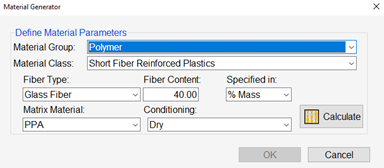
With the new FKM template, fatigue assessment has never been easier. Loaded directly from the user-friendly graphical user interface (GUI), this template allows for automatic fatigue assessment according to the seventh edition of the FKM guideline. FEMFAT takes care of the complex calculations, streamlining the process and saving you valuable time. Experience the convenience and accuracy of our FKM template as it revolutionizes your fatigue analysis workflow. - Material Generator for short fiber reinforced plastics
Select the material group “polymers” to start the Material Generator for fiber reinforced plastics. The new material is computed based on the input data fiber type, fiber content in % mass (% volume data are converted to mass %), matrix material and conditioning. The static and cyclic strength data both parallel and perpendicular to the fiber direction are then computed. This comprehensive material information allows you to explore the potential of fiber reinforced plastics in your designs.
- MAX: new PLAST method with exact sequence influence
This groundbreaking new technique ensures accurate analysis results by considering the exact sequence influence in your simulations. - Interfaces: support of Abaqus 2023 & MSC NASTRAN hdf5 files
We continuously strive to improve our software's compatibility with popular analysis software. In our latest release, we extend our interface support to Abaqus 2023 and MSC NASTRAN hdf5 files. - WELD: databases for DVS1612 and FKM 2020
Our commitment to providing comprehensive and accurate data continues with the addition of new databases for WELD. We now offer databases for DVS1612 and FKM 2020 welding standards. Accessing these welding guidelines and specifications has never been easier, empowering you to achieve reliable and efficient weld analysis. - SPECTRAL: improvements for modal stress data definition
We have listened to your feedback and made significant improvements to the SPECTRAL module. We are excited to introduce enhancements in modal stress data definition, allowing you to specify the load case with the modal stress results. This means stress files containing load cases, such as assembly conditions, in addition to the natural frequency analysis are now fully supported.
Introducing an enhanced Neuber approach with new PLAST method
We are excited to announce a new FEMFAT plast method that takes accuracy to the next level, all while considering the precise sequence influence. This breakthrough is made possible through the integration of a kinematic hardening model, adding an extra layer of sophistication to our simulation capabilities.
FEMFAT plast is available since many years and offers an efficient and reliable implementation of the Neuber method.
This method involves extracting stress data from a linear elastic finite element analysis and then approximating the non-linear elasto-plastic stresses. In simpler terms, it is employed to evaluate local plastic deformation, particularly in regions like notches. By accounting for localized plastic deformation, it provides a more accurate representation of stress distribution, leading to improved predictions of fatigue life.
The method offers significant advantages since a finite element simulation with elasto-plastic material behavior can be avoided in many applications.
So, what exactly does the new PLAST method bring to the table?
1. Enhanced Accuracy: The new method is designed to offer unparalleled accuracy in predicting metal plasticity behavior. By incorporating the kinematic hardening model, FEMFAT plast can capture the intricate details of how materials respond to variable amplitude loading, resulting in more precise simulations and predictions.
2. Sequence Influence: One of the key advantages of our new approach is its ability to account for the exact sequence influence of transient stress histories. There are two options available, stress rearrangement according Neuber or ESED (equivalent strain energy density). With our new method, you can gain insights into how materials evolve over time, enhancing the realism of your simulations.
3. Improved Consistency: The new PLAST method uses the selected equivalent stress method (e.g. Scaled Normal Stress). Additionally, now the rainflow counting comes after the stress rearrangement. In other words, the Neuber correction is directly applied in the cutting plane.
4. Additional Output: FEMFAT offers new output in terms of diagrams and text files. Now you can analyze strain histories as well as stress-strain diagrams.
For illustration of the new PLAST method a simple example of a notched specimen under pulsating tensile load (stress ratio R=0 ) is presented here. The fatigue analysis is carried out with both FEMFAT 2023 (new PLAST method) and FEMFAT 2022 (old PLAST method).
Examining the results, we can see significant differences in the equivalent stress histories:
- The old PLAST method delivers a pulsating stress response with constant amplitude like the original input signal (cp. figure 1).
- In contrast, the new method initially delivers decreasing amplitudes until they stabilize and remain constant due to material hardening (cp. top diagram in figure 2).
Additionally, the new PLAST method comes with diagrams for strain histories and stress/strain hysteresis (cp. figure 3).
")
Figure 1: Detailed Results for old PLAST method (history charts for equivalent stress, partial & total damage)
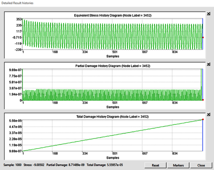
Figure 2: Detailed Results for new PLAST method (history charts for equivalent stress, partial & total damage)
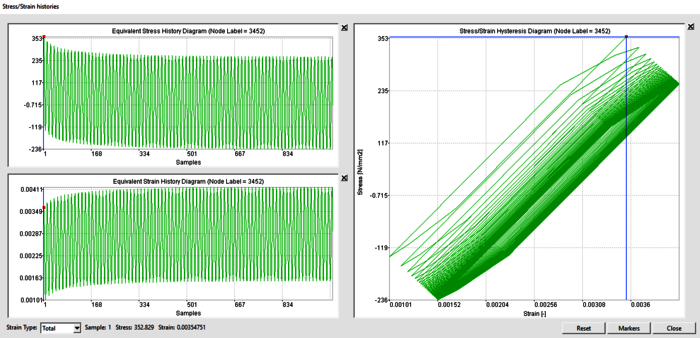
Figure 3: Detailed Results for new PLAST method (history charts for equivalent stress & strain, stress/strain hystereses)
In conclusion, our latest innovation in metal plasticity handling represents a significant step forward in the field of materials simulation. The incorporation of a kinematic hardening model and the consideration of sequence influence further increase both accuracy and reliability of FEMFAT results. Additionally, the new development helps saving time since an elasto-plastic material definition in FEA can be avoided in many cases.
Frequently Asked Questions
FAQ 1: Which Definition of the Stress-Strain Curve is used for the PLAST Method?
VIEW ANSWER
FAQ 2: What should the solver deck in Optistruct look like for a modal fatigue analysis with SPECTRAL?
VIEW ANSWER
BACK TO OVERVIEW
